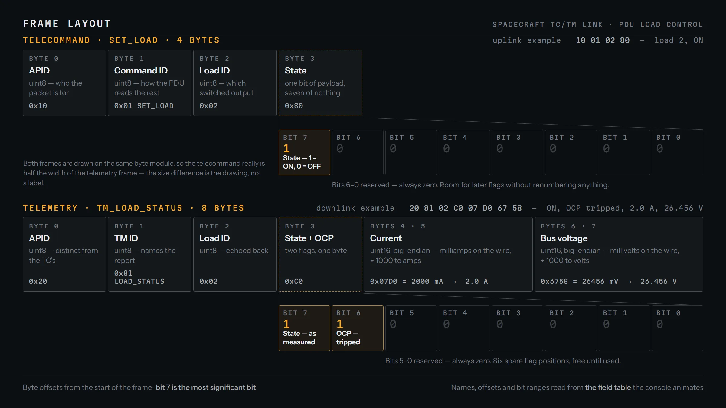
- Telecommand frame
- 4 bytes
- Telemetry frame
- 8 bytes
- Scenarios covered
- Nominal, OCP fault, shutdown
Interactive · Ground segment
One command, one reply, and the decision the ground has to make
The real 4-byte telecommand and 8-byte telemetry frame from this project, assembled and decoded field by field. Step through it.
Ground · EGSE
Telecommand · 4 bytes
- ——0
- ——1
- ——2
- ——3
Limit evaluation
Decision
Link
Spacecraft · PDU
Receive buffer
read blocked, waiting for the rest of the frame
Telemetry · 8 bytes
- ——0
- ——1
- ——2
- ——3
- ——4
- ——5
- ——6
- ——7
logs/test.csv
| timestamp | bus_voltage_v | current_a | ocp | decision | reason |
|---|---|---|---|---|---|
| — | 28.0 | 2.0 | 0 | KEEP_ON | all nominal |
| — | 26.456 | 2.0 | 1 | SHUTDOWN | voltage 26.456V < 26.5V; OCP flag set |
| — | 28.0 | 0.0 | 0 | OFF_CONFIRMED | shutdown command executed |
| — |
The timestamp column is left blank because this is a reconstruction. Inventing a time would put one fabricated value on an otherwise real page.
Your turn: feed it a telemetry frame
Eight bytes, as if the PDU had just sent them. The ground will decode them, apply the same limits, and issue whatever telecommand follows.
Eight bytes. Spaces optional.
Full transcript, all 41 steps
Nominal
21 stepsAct 1 · Nominal
The ground commands the load on and the PDU reports a healthy bus. This is what agreement between the two sides looks like.
Byte 0 · APID
The first byte says who this packet is for. A spacecraft runs dozens of processes and the router has to make that decision without opening the payload, so identity comes before content.
Byte 1 · Command ID
Which command it is. 0x01 is SET_LOAD, and it is what tells the PDU how to read the remaining two bytes. Get this byte wrong and everything after it is misinterpreted rather than rejected.
Byte 2 · Load ID
Which switched output to act on. Fixed at 2 here, but a full byte wide because a real power distribution unit has many, and addressing them is not something you want to redesign later.
Byte 3 · one bit of payload
The command carries its entire payload in bit 7: 1 means ON. Shifting a 1 up seven places gives 0x80.
Byte 3 · the seven reserved bits
Bits 6 to 0 are reserved and always zero. Spending seven bits to carry one looks wasteful until you need to decode a frame with no parser and no room for ambiguity: a fixed layout is readable by inspection, and the spare bits cost nothing until a future flag needs them.
Telecommand ready
Four bytes, fully determined, no length field and no delimiter. Both ends already agree a SET_LOAD is exactly 4 bytes, so the frame does not need to describe itself.
Uplink
The bytes go out over a TCP socket. What arrives at the other end is a stream of bytes with no message boundaries in it. The frame is a fiction both ends agree to maintain.
Three bytes arrive, and the reader blocks
TCP delivered three bytes, not four. A single read returns whatever happened to arrive, so the receiver loops until it has the count it asked for. Treating one read as one message is the most common way to get this wrong, and it fails intermittently rather than immediately.
Frame complete
The fourth byte arrives and the read returns. Only now does the PDU have something it is allowed to call a telecommand.
The PDU decodes it
Shift bit 7 down, mask off the rest: state = 1. The PDU switches load 2 on and measures the result.
Telemetry header
A different APID for the downlink, and a TM ID of 0x81, LOAD_STATUS. That second byte is the promise that bytes 4 to 7 are a current and a voltage; without it the numbers are unlabelled.
Byte 3 · two flags, one byte
State in bit 7, OCP in bit 6, combined with an OR. Here the byte is 0x80: the load is on and protection has not tripped. Packing status as bits rather than bytes saves downlink bandwidth, which is the scarcest resource a spacecraft has.
Bytes 4-5 · current
Two bytes, high byte first, because the convention is big-endian. 0x07 0xD0 is 2000, and the unit is milliamps, so 2.0 A. Integers rather than floats: the wire has no decimal point, and milli-units give a thousandth of resolution inside a 16-bit range.
Bytes 6-7 · bus voltage
Same encoding: 28000 mV, or 28.0 V. A 16-bit millivolt field tops out at 65.5 V, which is comfortable headroom over a 28 V bus while still resolving a single millivolt.
Downlink
Eight bytes back the other way. The ground reads all eight before acting on any of them, for the same reason the PDU read all four.
What the ground now believes
State 1, OCP 0, 2.0 A, 28.0 V, decoded from the frame rather than the command that provoked it. That distinction carries the design: an acknowledged telecommand is not an executed one, so the ground never updates its model of the spacecraft from what it sent.
Check 1 of 3 · Bus voltage
28.0 V clears the 26.5 V floor.
Check 2 of 3 · Load current
2.0 A against a 1.8–2.2 A window. The window has a floor as well as a ceiling: a load drawing far less than expected is as much a fault as one drawing too much.
Check 3 of 3 · OCP flag
Overcurrent protection has not tripped.
Verdict · KEEP_ON
Every limit holds, so the load stays on and the row is written: "all nominal". The log is the deliverable. You cannot go and look at a spacecraft, so an unrecorded decision may as well never have been made.
Fault — OCP tripped
11 stepsAct 2 · Fault — OCP tripped
The same command, a very different answer: the load still reports ON while its overcurrent protection has tripped and the bus is sagging.
The same four bytes again
An identical telecommand: same APID, same command, same load, bit 7 set. Nothing about the request has changed, which is what makes the answer interesting.
Up and decoded
Same four bytes, same read-until-you-have-four on the far side. The PDU switches load 2 on and measures the result.
Byte 3 · a frame that contradicts itself
Both flags are set, so the status byte is 0xC0. The load claims to be ON while its overcurrent protection has tripped. Nothing in the protocol prevents a frame from carrying a contradiction, which is why the ground checks more than one field before believing it.
The measurements
2.0 A at 26.456 V. The current is unremarkable; the bus has sagged below where the ground will tolerate it. Encoded the same way as before, since the layout does not change because the news is bad.
Down and decoded
Eight bytes back to the ground, read the same way.
What the ground now believes
State 1, OCP 1, 2.0 A, 26.456 V, decoded from the frame rather than the command that provoked it. The command it sent has no vote here.
Check 1 of 3 · Bus voltage
26.456 V is under the 26.5 V floor by 44 millivolts, the kind of margin a limit exists to catch.
Check 2 of 3 · Load current
2.0 A, still inside the window. The current is the one thing about this frame that looks entirely normal.
Check 3 of 3 · OCP flag
The OCP flag is set. It is independent of the voltage reading and catches the same fault a second way, which is why the frame carries both.
Verdict · SHUTDOWN
Two independent limits failed, and the reason string carries both: "voltage 26.456V < 26.5V; OCP flag set". The ground commands the load off without asking permission or waiting for an operator. That decision is what causes act 3.
Shutdown confirmed
9 stepsAct 3 · Shutdown confirmed
This act happens only because the ground decided it should. The load reports OFF and the bus recovers.
One bit changes
The same frame with bit 7 cleared. Byte 3 goes from 0x80 to 0x00, and that single bit is the entire difference between switch on and switch off.
Up and decoded
Same four bytes, same read-until-you-have-four on the far side. The PDU switches load 2 off and measures the result.
Byte 3 · the load reports off
Bit 7 is clear: the load is off. The status byte is 0x00, and that is positive evidence the shutdown took effect, rather than a record that it was sent.
The measurements
0.0 A at 28.0 V. No current, and the bus has recovered to its nominal value now the load is off.
Down and decoded
Eight bytes back to the ground, read the same way.
What the ground now believes
State 0, OCP 0, 0.0 A, 28.0 V, decoded from the frame rather than the command that provoked it. The command it sent has no vote here.
Not evaluated, confirmed
The limits are not applied here, on purpose. An idle load draws 0 A, which would fail the current window and be logged as a fresh fault. The ground commanded this shutdown, so the row records a confirmation instead. Re-evaluating your own instruction turns a success into an alarm.
Verdict · OFF_CONFIRMED
The load reports OFF and the bus has recovered. The row is logged as a confirmation: the ground now has evidence that the shutdown it ordered took effect, which is a different thing from having sent the command.
The problem
Spacecraft do not have a debugger attached. Every interaction with a subsystem in flight is a command sent up and a telemetry frame that comes back, and the ground segment’s entire job is to decide, from those bytes alone, whether what just happened was acceptable.
That constraint sets the rest. Frames are small and rigidly laid out, the failure modes have to be reachable on the ground, and every decision has to be recorded because you cannot go and look.
What I built
Two endpoints and the protocol between them.
The PDU simulator stands in for a satellite power distribution unit. It accepts load-control telecommands and answers with a status telemetry frame, including the case where overcurrent protection has tripped and the frame comes back reporting the load ON and its protection TRIPPED at the same time.
The ground client encodes commands, decodes the response, evaluates the reported state against safe operating limits, and writes its verdict to a log.
Three scenarios run end to end: a nominal load enable, a fault where the telemetry contradicts itself and has to be caught on two independent checks, and a commanded shutdown that has to be positively confirmed rather than assumed.
The rule the client is built around
The socket code is the boring half. The design rule underneath it is that the client must never assume its command worked. A telecommand that is acknowledged is not a telecommand that was executed, and a system built on that assumption fails silently in the situation where you can least afford it.
So the client’s model of the spacecraft is only ever updated from returned telemetry, and never from what it just sent. The confirm-gates in my robotics work come from the same principle: the state of the world is whatever the sensor reports, not whatever you told it to be.
Where a bench like this gets used
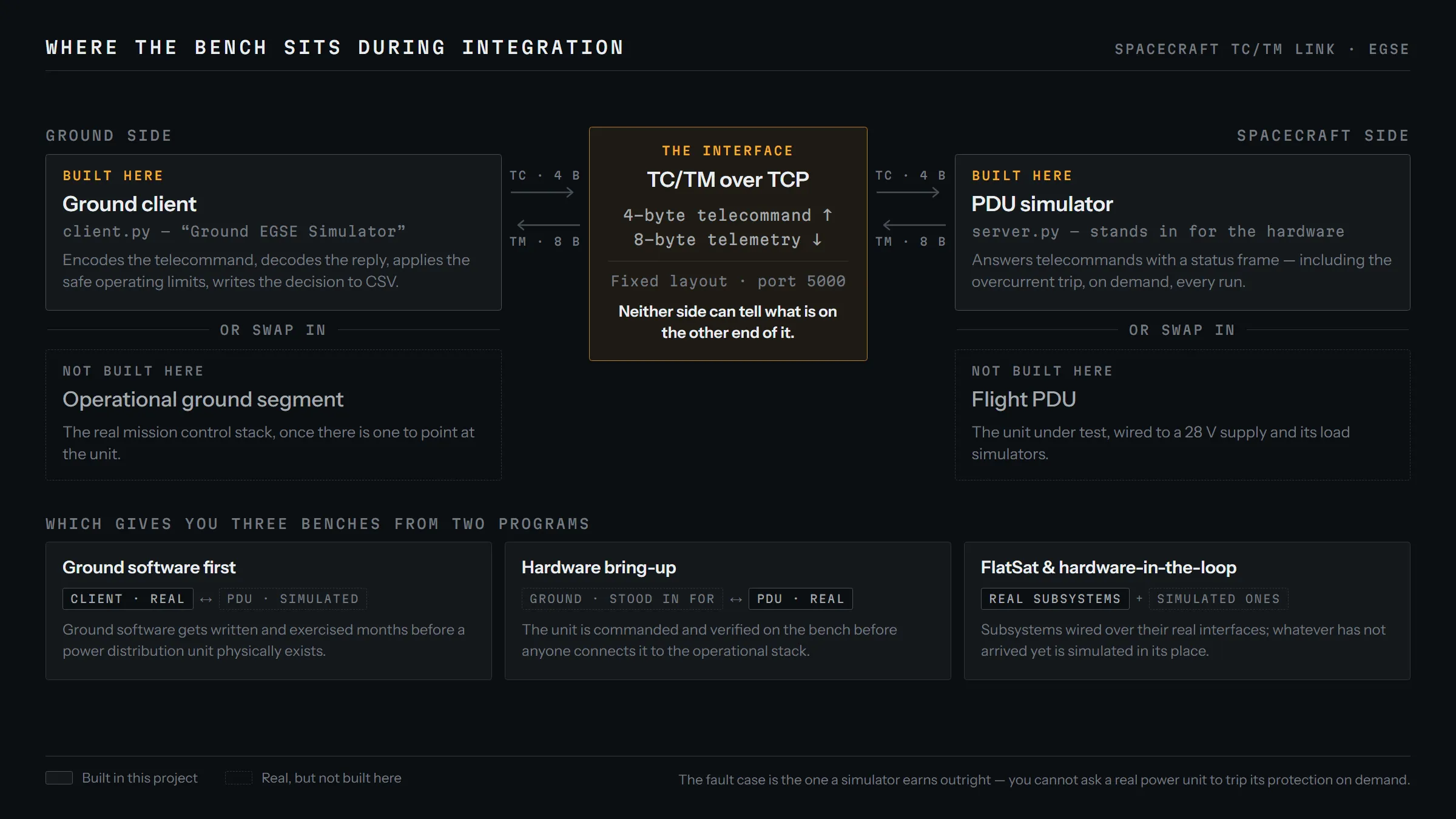
This is EGSE, electrical ground support equipment: two tools built from the same protocol pointed in opposite directions.
During spacecraft assembly, integration and test, the flight hardware and the ground software are almost never ready at the same time. The subsystem simulator lets ground software be written and exercised months before a real power distribution unit exists. The ground client does the reverse: when the PDU arrives on the bench, it can be commanded and verified before anyone connects it to the real mission control stack. On a FlatSat, the integration bench where subsystems are laid out flat and wired over their real interfaces, both halves run at once.
The fault scenario is where the bench earns its keep. You cannot ask an expensive power unit to trip its overcurrent protection on demand just to check that the ground reacts correctly. A simulator can produce that frame on every run, which makes the failure path testable instead of hypothetical. The same applies to hardware-in-the-loop work on the power system itself, and to procedure rehearsal, where operators practise responding to a fault nobody wants to stage for real.
The CSV earns its place too. In a verification campaign the artifact you hand over is evidence that a decision was made, on what data, and at what time, which is what that file records.
The problem statement came from an industry brief. The protocol design, both implementations, the fault scenarios and the containerised harness are mine.
Media
How this was built
The spec sheet above lists the stack. This section covers how the work was run, which a screenshot cannot show you.
Where AI did the work
- Wrote the frame layout and the encode/decode pair against it in one pass, so the two endpoints were generated from a single written spec rather than converging by trial and error.
- Treated the fault scenarios as the specification of correctness. The simulator was built to make them reachable.
The discipline around it
- The whole thing runs from one Docker Compose command with no host dependencies. A harness that takes an afternoon to set up gets used once.
- Every command-and-response exchange writes a row to a CSV with the decision that was made, so a run can be audited afterwards instead of only watched live.
What stayed human
- The safe-operating-limit thresholds are hand-specified. The client's job is to evaluate against them, never to infer what "safe" means.